Step 1. Construct a plaintext corpus (50k to 100k
characters of text). For example, you could
save this document to an ASCII file, then read in the file,
convert it to uppercase, and discard all characters not in
the alphabet {A-Z}. This
would be a useful technique for alphabet A only. Other methods
would be required to filter the characters in alphabets B-E.
Choose a subset of the plaintext corpus and encrypt it to
form the "unknown" ciphertext.
Step 2. Compute the n-gram (symbol, digram, trigram, etc.)
probability distributions from histograms that you compute given
the plaintext corpus you constructed in Step 1. From the
probability distributions, you can compute statistical measures
associated with each histogram (e.g., mean, mode, median, and
standard deviation).
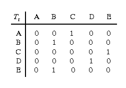
Step 3. Construct each rotor's transform in order to specify
the rotor machine, then formulate the adjacency matrix for each
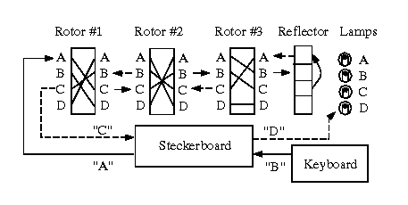
rotor transform as shown above. Thus, if you have n=3 rotors,
there will be three adjacency matrices. Initialize the matrices
to the values discussed in the preceding observation. Additionally,
you will want to assume odometer gearing only, i.e., each rotor
advances one symbol or position for each complete revolution of
the next-less-significant rotor. And, you will need to specify
the rotor initial position as a known quantity. Otherwise, you
will have to guess the correct position given |F|n
possible alternatives. For purposes of efficiency, start with a
simple rotor machine (i.e., |F| < 5 and n < 3), with
no Steckerboard or reflector.
Step 4. In order to constrain the optimization process, you
need a merit function, also called an objective function
in optimization theory. This function (which we denote as f)
tells you how close you
are to satisfying the constraint that directs your MLE-based
optimization. For example, in this case, the objective function
could compute the norm of the difference between the probability
distributions of the
candidate (decrypted) plaintext Pr(b) and the known
(corpus) plaintext Pr(a) as
f(a,b) = || Pr(a) - Pr(b) ||
= [(Pr(a) - Pr(b))2]1/2 .
Clearly, one would want to minimize this difference.
Note that the objective function
can also be formulated from statistical parameters such as the
mean, mode, standard deviation, etc., as well as from the
histograms (or probability distributions) of various n-grams
(e.g., digrams, trigrams, etc.)
Step 5. Apply the MLE approach discussed in class as follows:
a) Perturb one or more coefficients of the adjacency
matrix. Then, threshold the adjacency matrix by setting to
unity only those values larger than a given threshold value
T. For example, in the initial perturbation step, you might
increase one value in each row to 0.6, to form the adjacency
matrix of a bijection. A threshold value of 0.5 would then
suffice to produce a Boolean-valued adjacency matrix.
b) Configure your rotor machine
according to the transforms described by the adjacency matrices
you computed in Step 5a),
and apply the rotor machine decryption to the ciphertext obtained
in Step 1. This yields a trial decryption b.
c) Apply your objective function to b to obtain a
difference score between statistical measures derived from
b and the plaintext corpus.
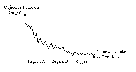
The goal of the first few iterations of steps 5a) through 5c) is to
obtain a large decrease in the output of your
objective function. Since you want to approach a
near-zero difference in the objective function output as
quickly as possible, this
implies fast convergence in the initial iterations of the
MLE optimization process, as shown in Region A of Figure 5.
In subsequent iterations, you will need to time average the
output of the objective function f by averaging f's
output over the last K iterations. Averaging is essential to
remove the oscillations shown in Region B of Figure 5. Without
averaging, you will not be able to reach a minimum in
f's output.

Figure 5. Hypothetical objective function output that
schematically illustrates
zones of convergence in a constraint-based
optimization problem.
Step 6. After you pass through Region B (slow, oscillatory
decrease in f's output), one usually encounters smaller
oscillations in Region C, where the average output of f
decreases very slowly and the rate of convergence approaches zero.
(In order to compute the rate of convergence, take the
first derivative with respect to time of the time average of
f's output. You may even want to average these derivatives
over a few samples, to remove unwanted noise.)
When the rate of convergence brings the average of f's output
to within some limit  of zero, then it is time to stop the MLE process. In practice,
the choice of
  depends
largely upon the quantization error inherent in the n-gram
histograms that are employed in computing f. Although this is
not usually a problem for large plaintext corpi and ciphertext
samples, you may have to choose your ciphertext to be several
thousand characters, in order to obtain an average quantization
error that is within, say, two percent of full scale (which
equals an error of 0.02 in a probability distribution). It would
be helpful for you to recall
the discussions we had in class about quantization error and analysis
of error. Then, use that theory to predict the limiting error with
which various symbols can be determined from histogram data.
Step 7. When you have recognizable words or phrases in b,
this can also be a sign that the MLE process is coming to a
convergence point. At this point, you may want to stop the MLE
algorithm and guess the remainder of the text. From the guessed
text and the known ciphertext, you can confirm the rotor machine's
configuration. A glance at your solution to Homework Problem 1.1
(Vigenere cipher) may help you here.
Be aware that the MLE process usually does not produce a perfect decryption,
due to quantization error, computational errors, and erroneous initial
assumptions. However, with practice (starting with a one-rotor machine
over a very small alphabet), you will be able to obtain reasonably efficient
guesses at rotor machine configurations.
 domain(a) ,
  (I)
(I)


 |
| 

 ,
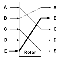
the rotor transform Tr: F -> F
has an adjacency matrix representation M denoted by


 of zero, then it is time to stop the MLE process. In practice,
the choice of