- Step 1. Set LIMITS to (0.0,0.0) in the lower left-hand
corner of the drawing, and (8.5,11.0) in the upper right hand
corner. assume, for the purposes of this assignment, that one
AutoCAD drawing unit equals one inch. Set GRID and SNAP
spacing to 0.5 inches, then set GRID and SNAP to ON, in order
to display the grid and enable Snap to the Grid points. Set
ZOOM factor to 1.0, to see the grid.
Step 2. Set Zoom factor to 0.5, then draw a box 7 inches square using the RECTANGLE command.
Step 3. Set the Zoom factor to 1.0. In the lower right-hand corner of the box drawn in Step 2, draw a small box 1 inch high and 3 inches long.
Step 4. Draw two diagonal lines with 1.5 inch clearance (horizontal and vertical) from the corners of the large box. We will call the intersection of the two diagonal lines the Center Point of the outer box.
Step 5. Set the Zoom factor to 2.0, and the Snap and Grid spacing to 0.25. Disable AutoSnap by clicking on the OSNAP button on the lowest row of buttons on the AutoCAD interface. This will prevent the little yellow rectangle from appearing and making the following boxes too small.
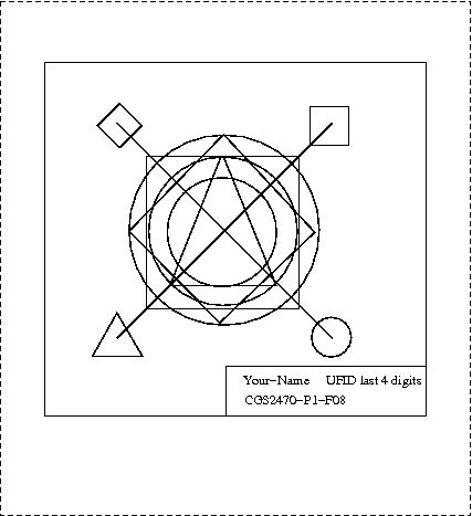
Draw the small box (approximately 1 inch diameter), which is centered on an endpoint of the diagonal line segment drawn in Step 4, as shown in Figure 1. Repeat this process for the small diamond (approximately 1 inch side length), circle, and triangle, per Figure 1. There should be a small amount of clearance between the circumference of each small circle or square and the upper left-hand corner of the text box drawn in Step 2 or 3, as shown in Figure 1. A similar comment holds re: clearance with between the small objects and the bounding box.
Step 6. Draw one large circle centered on the intersection of the two diagonal lines, as shown in Figure 1. Next, draw a box outside the circle and a diamond inside the circle, both centered on the center of the circle, as shown in Figure 1. Additionally, draw a triangle as shown in Figure 1.
Also, draw a circle inside the diamond that is centered on the intersection of the two diagonal lines, and whose perimeter touches but does not overflow the sides of the inner diamond (the latter constraint is not correctly illustrated in Figure 1, due to a graphics rendering error). You may have to disable SNAP to do this, by clicking on the button labelled SNAP at the bottom of the AutoCAD interface.
Step 7. After setting SNAP to the OFF position, set the TEXT height parameter to 0.15 inches. Then, place your last name and last four digits of your UF-ID in the top half of the box drawn in Step 3. In the bottom half of the box, place the following text: "CGS2470-P1-F08". You may need to decrease the text size to fit your last name in the box, if you have a long name. Do not use your Social Security Number, or any part of it, to identify yourself. Similarly, do not use your complete UF-ID.
Step 8. Center the figure in the center of your paper, using the Scale, Rotate, and Offset features of the PRINT command (or Scale, Zoom, and Pan controls of the Print Preview feature).

Figure 1. CGS2470 - Project #1: Lines, Circles, and Text
(not drawn to scale). Dotted lines denote edges of paper.
Hardcopy. The completed project (drawing) should be printed on a high-quality inkjet printer or laser printer. A laser printer is not required for this first project. A good place to print your drawings is any of the CIRCA computer labs.
Items Due. Give the instructor your completed project in class on Thu 11 September 2008. Projects turned in a day late will be penalized -10%; two days late: -20%. Projects turned in more than two days after the due date will not be accepted unless accompanied by a documented excuse (note from your physician or advisor).
Grading. The following point allocation will determine your grade for this project, subject to the instructor's judgement:
       REQUIRED FEATURE(S)                  POINTS
       -----------------------------------  ------
       Bounding box and text box, with text   15
       Diagonal lines  . . . . . . . . . .    10
       Circles, etc. at endpoints of lines    10
       Large circles . . . . . . . . . . .     5
       Large box . . . . . . . . . . . . .     5
       Diamond . . . . . . . . . . . . . .     5
       -------------------------------------------
       TOTAL POINTS                           50